Suggested Ampacities
Ampacity, or current carrying capacity, is defined as the current a conductor can carry before its temperature exceeds a permissible value. The correct conductor size ensures that the heat generated by the flow of current through the conductor and the heat of the ambient temperature does not exceed the thermal rating of the insulation.
There are many factors which will limit the amount of current that can be passed through a wire:
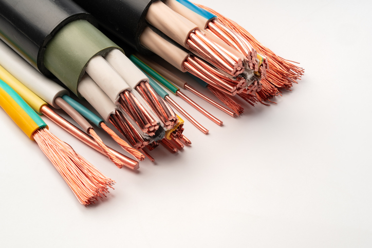
CONDUCTOR SIZE: The size of the conductor is a primary factor affecting the ampacity. The larger the circular mil area (a unit used to denote cross-sectional area), the higher the current-carrying capacity. Larger conductors can handle more current because they have less electrical resistance and generate less heat.
INSULATION: The type of insulation surrounding the conductor plays a critical role in determining its ampacity. The insulation must be able to withstand the heat generated by the electrical current. Exceeding the maximum temperature rating of the insulation can lead to degradation, reducing the conductor's effectiveness and potentially causing safety hazards.
NUMBER OF CONDUCTORS: When multiple conductors are bundled together the heat generated by each conductor is less effectively dissipated. As the number of individually insulated conductors in a bundle increases, the ability to dissipate head decreases which reduces the overall ampacity.
INSTALLATION CONDITIONS: Restricting heat dissipation by installing the conductors in conduit, duct, trays or raceways lessens the current carrying capacity. This restriction can be alleviated by using proper ventilation methods, forced air cooling, etc.
Assigning a current rating to a wire is essentially a heat transfer problem. Without overheating the conductor or insulation, the watts produced at the conductor must be dissipated through the insulation to the ambient.
While organizations like the Insulated Cable Engineers Association and the National Electric Code have formally issued current ratings for power cables, no such ratings have been produced for appliance wires or equipment cables.
It is nearly impossible to standardize actual current ratings since appliance and device designs vary so greatly.
Reelsmart AI Assistant is IEWC’s on-demand resource—designed to help you quickly find answers to questions about wire, cable, and wire management solutions. It delivers information to help you better understand products, specifications, and applications. Ready to find what you need faster? Try Reelsmart AI Assistant now.
SUGGESTED AMPACITIES (All Types of Single Conductor Insulation)
| AWG | 80C | 90C | 105C | 125C | 150C | 200C | 250C* |
|---|---|---|---|---|---|---|---|
| AMPERES PER CONDUCTOR | |||||||
| 30 | 2 | 3 | 3 | 3 | 3 | 4 | 4 |
| 28 | 3 | 4 | 4 | 5 | 5 | 6 | 6 |
| 26 | 4 | 5 | 5 | 6 | 6 | 7 | 8 |
| 24 | 6 | 7 | 7 | 8 | 8 | 10 | 11 |
| 22 | 8 | 9 | 10 | 11 | 12 | 13 | 14 |
| 20 | 10 | 12 | 13 | 14 | 15 | 17 | 19 |
| 18 | 15 | 16 | 18 | 20 | 22 | 24 | 29 |
| 16 | 18 | 20 | 24 | 26 | 29 | 32 | 37 |
| 14 | 20 | 25 | 33 | 40 | 40 | 45 | 39 |
| 12 | 25 | 30 | 45 | 50 | 50 | 55 | 54 |
| 10 | 35 | 40 | 58 | 70 | 70 | 75 | 73 |
| CORRECTION FACTORS FOR VARIOUS AIR TEMPERATURES | |||||||
|---|---|---|---|---|---|---|---|
| 30 | 1.00 | 1.00 | 1.00 | 1.00 | 1.00 | 1.00 | 1.00 |
| 40 | 0.88 | 0.90 | 0.92 | 0.95 | 0.96 | 0.97 | 0.98 |
| 50 | 0.75 | 0.80 | 0.82 | 0.89 | 0.91 | 0.93 | 0.95 |
| 60 | 0.58 | 0.67 | 0.73 | 0.83 | 0.87 | 0.91 | 0.95 |
| 70 | 0.35 | 0.52 | 0.61 | 0.76 | 0.82 | 0.87 | 0.93 |
| 80 | - | 0.30 | 0.46 | 0.69 | 0.76 | 0.84 | 0.90 |
| 90 | - | - | 0.30 | 0.61 | 0.71 | 0.80 | 0.87 |
| 100 | - | - | - | 0.51 | 0.65 | 0.77 | 0.85 |
| 125 | - | - | - | - | 0.50 | 0.66 | 0.72 |
| 150 | - | - | - | - | - | 0.54 | 0.65 |
| 200 | - | - | - | - | - | - | 0.49 |
This table shows the suggested ampacities for all types of single conductor insulation including amperes per conductor and correction factors for various air temperatures. Current ratings for different conductor materials may be calculated by multiplying the appropriate copper conductor ratings by the following factors:
*NICKEL PLATED COPPER: 0.87
NICKEL: 0.43
Suggested Current Carrying Capacity Table (Base Temperature at 40C)
|
150C
| 200C
Tinned Copper NPC 2% - 10% | 250C
NPC 2% - 10% | 250C
"A" Nickel | 250C
NPI | 450C
NPC - 27% | 450C
"A" Nickel | |
|---|---|---|---|---|---|---|---|
| 24 | 6.6 | 7.2 | 8 | 4 | 3.3 | 9 | 4.3 |
| 22 | 9 | 9.6 | 10.8 | 5 | 4.4 | 12 | 5.6 |
| 20 | 13 | 14 | 15 | 7 | 6 | 18 | 8 |
| 18 | 17 | 18 | 20 | 9.4 | 8 | 23 | 11 |
| 16 | 22 | 24 | 26 | 12 | 11 | 30 | 14 |
| 14 | 34 | 36 | 39 | 18 | 16 | 45 | 21 |
| 12 | 43 | 45 | 54 | 25 | 22 | 56 | 26 |
| 10 | 55 | 60 | 73 | 34 | 30 | 75 | 35 |
| 8 | 76 | 83 | 93 | 43 | 39 | 104 | 49 |
| 6 | 96 | 110 | 117 | 55 | 49 | 138 | 65 |
| 4 | 120 | 125 | 148 | 69 | 62 | 162 | 76 |
| 3 | 143 | 152 | 166 | 78 | 69 | 182 | 85 |
| 2 | 160 | 171 | 191 | 90 | 80 | 210 | 99 |
| 1 | 186 | 197 | 215 | 101 | 90 | 236 | 110 |
| 1/0 | 215 | 229 | 244 | 114 | 102 | 268 | 126 |
| 2/0 | 251 | 260 | 273 | 128 | 114 | 300 | 141 |
| 3/0 | 288 | 297 | 308 | 144 | 129 | 338 | 159 |
| 4/0 | 332 | 346 | 361 | 169 | 151 | 397 | 186 |
| 250 | 365 | 385 | 398 | 187 | 167 | - | - |
| 300 | 414 | 436 | 452 | 212 | 190 | - | - |
| 350 | 461 | 486 | 503 | 236 | 211 | - | - |
| 400 | 495 | 522 | 540 | 254 | 226 | - | - |
| 500 | 563 | 593 | 613 | 288 | 257 | - | - |
This table shows the suggested current carrying capacities with a base temperature at 40 degrees Celsius.
NOTE: For allowable ampacities for fixture wire, please see the National Electrical Code Handbook.
For ambient temperatures other than 40C (104F), multiply the ampacities shown above by the appropriate factor shown below.
Wire Temperature Rating
| Ambient Temperature (C) | 200C | 250C | 450C | Ambient Temperature (F) |
|---|---|---|---|---|
| 41-50 | 0.97 | 0.98 | 0.99 | 106-122 |
| 51-60 | 0.94 | 0.95 | 0.99 | 124-140 |
| 61-70 | 0.90 | 0.93 | 0.96 | 142-158 |
| 71-80 | 0.87 | 0.90 | 0.95 | 160-176 |
| 81-90 | 0.83 | 0.87 | 0.93 | 177-194 |
| 91-100 | 0.72 | 0.85 | 0.92 | 195-212 |
| 101-120 | 0.71 | 0.79 | 0.89 | 213-248 |
| 121-140 | 0.61 | 0.71 | 0.86 | 249-284 |
| 141-160 | 0.50 | 0.65 | 0.84 | 285-320 |
| 161-180 | 0.35 | 0.58 | 0.81 | 321-356 |
| 181-200 | - | 0.49 | 0.78 | 357-392 |
| 201-225 | - | 0.35 | 0.74 | 393-437 |
| 226-250 | - | - | 0.69 | 439-482 |
| 251-275 | - | - | 0.65 | 483-527 |
| 276-300 | - | - | 0.60 | 528-572 |
| 301-325 | - | - | 0.55 | 573-617 |
| 326-350 | - | - | 0.49 | 618-662 |
| 351-375 | - | - | 0.42 | 663-707 |
| 376-400 | - | - | 0.34 | 708-752 |
NOTE: The use of this table for establishing ampacity ratings is an inexact procedure. This table should only be used as a starting point when establihsing ratings for any given situations. It is recommended that design engineers desiring accurate ampacity data study the National Electrical Code Handbook - Article 310-13-310-84.
Suggested Ampacities (All Types of Insulations)
| COPPER | ALUMINUM | |||||||||||
| Not More Than 3 Conductors in Raceway or Cable | Single Conductor in Free Air | Not More Than 3 Conductors in Raceway or Cable | Single Conductor in Free Air | |||||||||
| CONDUCTOR TEMPERATURE RATINGS | ||||||||||||
| AWG or
MCM | 85-90C
Temp (185F) | 110C
Temp (230F) | 85-90C
Temp (185F) | 110C
Temp (230F) | 125C
Temp (257F) | 200C
Temp (392F) | 85-90C
Temp (185F) | 110C
Temp (185F) | 85-90C
Temp (185F) | 110C
Temp (230F) | 125C
Temp (257F) | 200C
Temp (392F) |
| AMPERES PER CONDUCTOR (100% LOAD FACTOR) | ||||||||||||
| 14 | 25 | 30 | 30 | 40 | 40 | 45 | - | - | - | - | - | - |
| 12 | 30 | 35 | 40 | 50 | 50 | 55 | 25 | 25 | 30 | 40 | 40 | 45 |
| 10 | 40 | 45 | 55 | 65 | 70 | 75 | 30 | 35 | 45 | 50 | 55 | 60 |
| 8 | 55 | 60 | 75 | 85 | 90 | 100 | 40 | 45 | 55 | 65 | 70 | 80 |
| 6 | 70 | 80 | 100 | 120 | 125 | 135 | 55 | 60 | 80 | 95 | 100 | 105 |
| 4 | 95 | 105 | 135 | 160 | 170 | 180 | 75 | 80 | 105 | 125 | 135 | 140 |
| 2 | 125 | 135 | 185 | 210 | 225 | 240 | 100 | 105 | 140 | 165 | 175 | 185 |
| 1 | 145 | 160 | 215 | 245 | 265 | 280 | 110 | 125 | 165 | 190 | 205 | 220 |
| 0 | 165 | 190 | 250 | 285 | 305 | 325 | 130 | 150 | 190 | 220 | 240 | 255 |
| 00 | 190 | 215 | 290 | 330 | 355 | 370 | 145 | 170 | 220 | 255 | 275 | 290 |
| 000 | 215 | 245 | 335 | 385 | 410 | 430 | 170 | 195 | 255 | 300 | 320 | 335 |
| 0000 | 250 | 275 | 390 | 445 | 475 | 510 | 195 | 215 | 300 | 345 | 390 | 400 |
| 250 | 275 | 315 | 440 | 495 | 530 | - | 220 | 250 | 330 | 385 | 415 | - |
| 300 | 310 | 345 | 485 | 555 | 590 | - | 250 | 275 | 375 | 435 | 460 | - |
| 350 | 340 | 390 | 550 | 610 | 655 | - | 270 | 310 | 415 | 475 | 510 | - |
| 400 | 365 | 420 | 595 | 665 | 710 | - | 295 | 335 | 450 | 520 | 555 | - |
| 500 | 415 | 470 | 675 | 765 | 815 | - | 335 | 380 | 515 | 595 | 635 | - |
| 600 | 460 | 525 | 750 | 855 | 910 | - | 370 | 425 | 585 | 675 | 720 | - |
| 700 | 500 | 560 | 825 | 940 | 1,005 | - | 405 | 455 | 645 | 475 | 795 | - |
| 750 | 515 | 580 | 855 | 980 | 1,045 | - | 420 | 470 | 670 | 775 | 825 | - |
| 800 | 535 | 600 | 885 | 1,020 | 1,085 | - | 430 | 485 | 695 | 805 | 855 | - |
| 900 | 565 | - | 950 | - | - | - | 465 | - | 750 | - | - | - |
| 1,000 | 590 | 680 | 1,020 | 1,165 | 1,240 | - | 485 | 560 | 800 | 930 | 990 | - |
This table shows the suggested ampacities for all types of insulation including conductor temperature ratings and amperes per conductor.
CORRECTION FACTORS FOR VARIOUS AMBIENT AIR TEMPERATURES
| 40C | 0.90 | 0.94 | 0.90 | 0.94 | 0.95 | - | 0.90 | 0.94 | 0.90 | 0.94 | 0.95 | - |
| 50C | 0.80 | 0.87 | 0.80 | 0.87 | 0.89 | - | 0.80 | 0.87 | 0.80 | 0.87 | 0.89 | - |
| 60C | 0.67 | 0.79 | 0.67 | 0.79 | 0.83 | 0.91 | 0.67 | 0.79 | 0.67 | 0.79 | 0.83 | 0.91 |
| 70C | 0.52 | 0.71 | 0.52 | 0.71 | 0.76 | 0.87 | 0.52 | 0.71 | 0.52 | 0.71 | 0.76 | 0.87 |
| 80C | 0.30 | 0.61 | 0.30 | 0.61 | 0.69 | 0.84 | 0.30 | 0.61 | 0.30 | 0.61 | 0.69 | 0.84 |
| 90C | - | 0.50 | - | 0.50 | 0.61 | 0.80 | - | 0.50 | - | 0.50 | 0.61 | 0.80 |
| 100C | - | - | - | - | 0.51 | 0.77 | - | - | - | - | 0.51 | 0.77 |
| 120C | - | - | - | - | - | 0.69 | - | - | - | - | - | 0.69 |
| 140C | - | - | - | - | - | - | 0.59 | - | - | - | - | 0.59 |
*Based on an ambient temperature of 30C (86F)
The table above shows the correction factors for various ambient air temperatures anywhere from 40 degrees Celsius to 140 degrees Celsius.
Related Resources
Basic Ampacity Values
Ampacity, or current carrying capacity, is defined as the current a conductor can carry before its temperature rise exceeds a permissible value.Learn More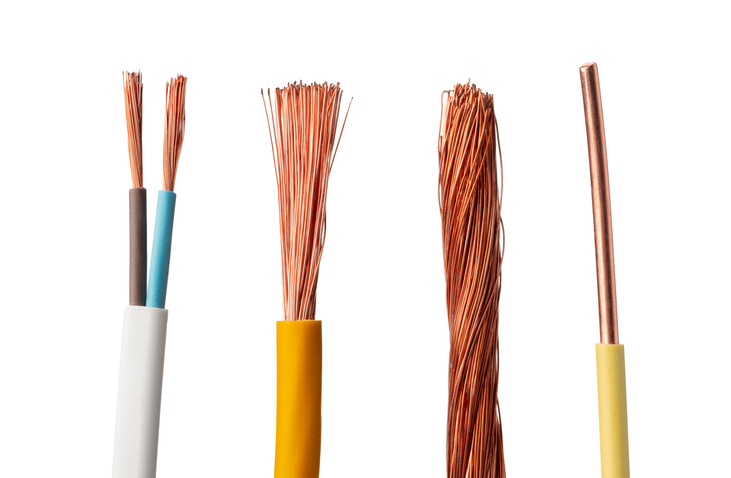
What is a Wire?
Wire refers to a single, usually cylindrical, strand or rod of metal which is used to carry electricity and telecommunications signals. Learn More
Cable Installation Guidelines
Care must be taken with any flexing application during the installation of the cable. Learn More