Color Codes
Guide to Electrical Color Codes: ICEA, NEMA, and Telephone Standards
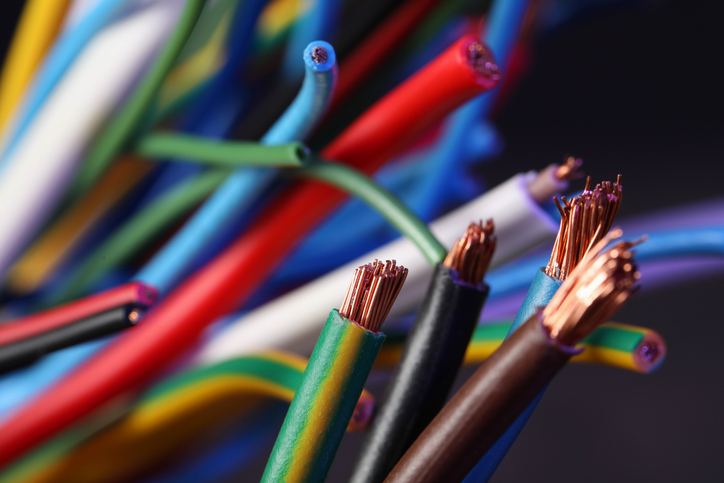
Understanding electrical color codes is vital for maintaining safety and efficiency in any electrical installation. This guide covers the color-coding methods set by the Insulated Cable Engineers Association (ICEA) and the National Electrical Manufacturers Association (NEMA), as well as telephone paired wiring color codes. Each standard specifies unique color schemes for electrical conductors and cables to simplify identification and installation.
ICEA Paired Cable Color Codes
The ICEA paired color code system organizes wires into pairs with specific color combinations to prevent confusion and ensure proper connectivity. Each pair consists of two legs, with one color representing each leg. Here is a breakdown of the color codes according to the ICEA standards:
- Pair 1: Black (Leg #1), White (Leg #2)
- Pair 2: Red (Leg #1), White (Leg #2)
- Pair 3: Green (Leg #1), White (Leg #2)
- Pair 4: Orange (Leg #1), White (Leg #2)
- Pair 5: Blue (Leg #1), White (Leg #2)
This pattern continues with various base colors paired with a white tracer or a combination of white and another base color. After 21 pairs, the color sequence repeats.
Reelsmart AI Assistant is IEWC’s on-demand resource—designed to help you quickly find answers to questions about wire, cable, and wire management solutions. It delivers information to help you better understand products, specifications, and applications. Ready to find what you need faster? Try Reelsmart AI Assistant now.
| Leg #1 | Leg #2 | ||
|---|---|---|---|
| Pair Number | Color | Tracer | Color |
| 1 | Black | - | White |
| 2 | Red | - | White |
| 3 | Green | - | White |
| 4 | Orange | - | White |
| 5 | Blue | - | White |
| 6 | White | Black | White |
| 7 | Red | Black | White |
| 8 | Green | Black | White |
| 9 | Orange | Black | White |
| 10 | Blue | Black | White |
| 11 | Black | White | White |
| 12 | Red | White | White |
| 13 | Green | White | White |
| 14 | Blue | White | White |
| 15 | Black | Red | White |
| 16 | White | Red | White |
| 17 | Orange | Red | White |
| 18 | Blue | Red | White |
| 19 | Red | Green | White |
| 20 | Orange | Green | White |
| 21 | Black | - | White |
NEMA & ICEA Method 1/K-1 Conductor Color Coding
The NEMA and ICEA Method 1/K-1 specifies a color-coding system for conductors to ensure uniformity and safety in electrical installations. The following are the conductor numbers and their corresponding color codes:
- Conductor 1: Black (Base Color)
- Conductor 2: White (Base Color)
- Conductor 3: Red (Base Color)
- Conductor 4: Green (Base Color)
- Conductor 5: Orange (Base Color)
From conductor 6 onwards, base colors are combined with tracer colors like black, red, or white to create distinct color codes. Beyond 21 conductors, the color code sequence starts again from the beginning.
| Conductor Number | Base Color | Tracer Color |
|---|---|---|
| 1 | Black | - |
| 2 | White | - |
| 3 | Red | - |
| 4 | Green | - |
| 5 | Orange | - |
| 6 | Blue | - |
| 7 | White | Black |
| 8 | Red | Black |
| 9 | Green | Black |
| 10 | Orange | Black |
| 11 | Blue | Black |
| 12 | Black | White |
| 13 | Red | White |
| 14 | Green | White |
| 15 | Blue | White |
| 16 | Black | Red |
| 17 | White | Red |
| 18 | Orange | Red |
| 19 | Blue | Red |
| 20 | Red | Green |
| 21 | Orange | Green |
NEMA & ICEA Method 1/K-2 Conductor Color Coding
NEMA & ICEA Method 1/K-2 provides another standard for conductor color coding. This method follows a similar pattern but uses a different set of base and tracer color combinations:
- Conductor 1: Black (Base Color)
- Conductor 2: Red (Base Color)
- Conductor 3: Blue (Base Color)
- Conductor 4: Orange (Base Color)
- Conductor 5: Yellow (Base Color)
Color combinations extend to include brown, and beyond conductor 21, the sequence repeats itself. This standard allows for easy differentiation of wires in complex systems and helps to avoid any miswiring.
| Conductor Number | Base Color | Tracer Color |
|---|---|---|
| 1 | Black | - |
| 2 | Red | - |
| 3 | Blue | - |
| 4 | Orange | - |
| 5 | Yellow | - |
| 6 | Brown | - |
| 7 | Red | Black |
| 8 | Blue | Black |
| 9 | Orange | Black |
| 10 | Yellow | Black |
| 11 | Brown | Black |
| 12 | Black | Red |
| 13 | Blue | Red |
| 14 | Orange | Red |
| 15 | Yellow | Red |
| 16 | Brown | Red |
| 17 | Black | Blue |
| 18 | Red | Blue |
| 19 | Orange | Blue |
| 20 | Yellow | Blue |
| 21 | Brown | Blue |
| 22 | Black | Orange |
| 23 | Red | Orange |
| 24 | Blue | Orange |
| 25 | Yellow | Orange |
| 26 | Brown | Orange |
| 27 | Black | Yellow |
| 28 | Red | Yellow |
| 29 | Blue | Yellow |
| 30 | Orange | Yellow |
| 31 | Brown | Yellow |
| 32 | Black | Brown |
| 33 | Red | Brown |
| 34 | Blue | Brown |
| 35 | Orange | Brown |
| 36 | Yellow | Brown |
Telephone Paired Wiring Color Codes
For telephone wiring, a distinct set of color codes is used to identify pairs of wires. Each pair consists of a "tip" conductor and a "ring" conductor. The color coding for these wires is critical in telephone installations to ensure accurate connectivity and functionality.
- Pair 1: White (Tip Conductor), Blue (Ring Conductor)
- Pair 2: White (Tip Conductor), Orange (Ring Conductor)
- Pair 3: White (Tip Conductor), Green (Ring Conductor)
- Pair 4: White (Tip Conductor), Brown (Ring Conductor)
- Pair 5: White (Tip Conductor), Slate (Ring Conductor)
The pattern continues up to 25 pairs, after which each group of 25 pairs is marked with colored or imprinted binders to distinguish them from other groups.
| Pair Number | Tip Conductor | Ring Conductor |
|---|---|---|
| 1 | White | Blue |
| 2 | White | Orange |
| 3 | White | Green |
| 4 | White | Brown |
| 5 | White | Slate |
| 6 | Red | Blue |
| 7 | Red | Orange |
| 8 | Red | Green |
| 9 | Red | Brown |
| 10 | Red | Slate |
| 11 | Black | Blue |
| 12 | Black | Orange |
| 13 | Black | Green |
| 14 | Black | Brown |
| 15 | Black | Slate |
| 16 | Yellow | Blue |
| 17 | Yellow | Orange |
| 18 | Yellow | Green |
| 19 | Yellow | Brown |
| 20 | Yellow | Slate |
| 21 | Violet | Blue |
| 22 | Violet | Orange |
| 23 | Violet | Green |
| 24 | Violet | Brown |
| 25 | Violet | Slate |
Related Resources
Jacket Selection
The jacket or sheath physically protects the internal components of a cable, improves the cables appearance, provides flame, mechanical, thermal, chemical and environmental protection to the conductors and components.Learn More
Popular Insulation Types
Insulation is a critical component of any wire conducting an electrical current . The right type of wire insulation is determined by numerous factors, including stability, required life, dielectric properties, temperature and moisture resistance, mechanical strength, and flexibility.Learn More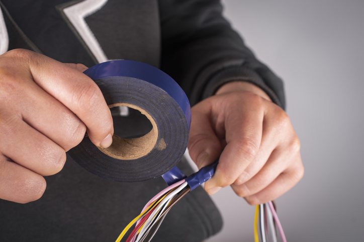
Tape Types
Plastic tapes are rarely used as a primary insulation in electronic wires because such wires, as compared with those having extruded insulations, are relatively expensive.Learn More