Managing Control Cable in High-EMI Environments
Control cables in high-EMI environments can pick up electrical noise from VFDs, motor starters, nearby power cables, and improper grounding. This interference can cause false signals, sensor drift, equipment faults, and unplanned shutdowns. Proper cable selection, shielding, grounding, and routing can reduce these risks and help maintain reliable control-system performance.
This guide explains the main sources of EMI, how different cable constructions help control interference, best practices for grounding and routing, and how to troubleshoot EMI problems in an existing installation.
Key Takeaways
- Common EMI sources include VFDs, motor starters, power cable proximity, and ground loops.
- Shielding, twisted-pair construction, and low-capacitance cable help address different “noise” problems.
- Proper grounding and shield termination prevent ground loops.
- 12 inches is the standard baseline for cable separation.
What Causes EMI in Control Cable Systems
EMI is a well-known issue in the cable industry. The right cable selection and shielding help prevent most issues long before they start. Grounding and maintenance close the gaps that selection alone can’t cover. For systems that already show symptoms of EMI, there’s a clear, diagnostic path to help you isolate and fix the source of the issue without undertaking a full replacement or re-cabling job.
It’s important to understand inductive coupling versus capacitive coupling. Inductive coupling occurs with a changing current in one wire (such as a motor cable). This creates a magnetic field that causes unwanted current in nearby wires—essentially, the two wires are “talking” to each other through the air.
Capacitive coupling occurs when you have a voltage difference in cables. Two wires may not be touching, but they still electronically interfere with each other because they’re in proximity—similar to the way static builds up between two surfaces.
Proximity and cable length can increase both types of coupling. So separation distance is a critical consideration. There are also several applications where EMI is more likely:
- VFDs
- Motor starters
- Power cable proximity
- Ground loops
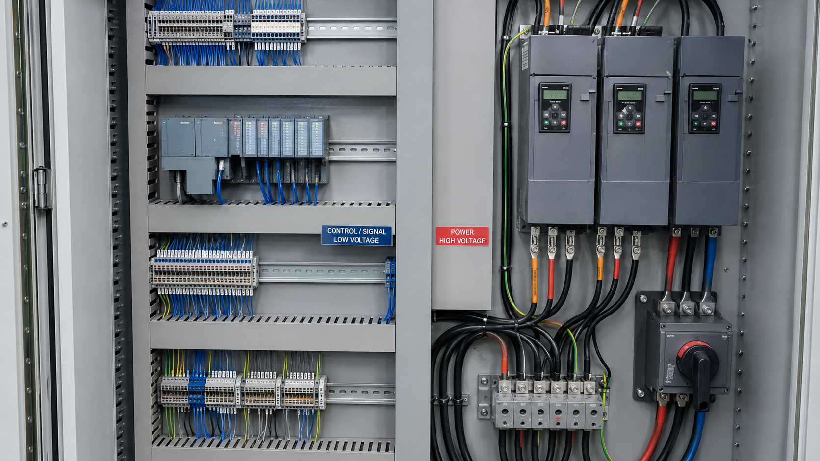
VFDs are used to control motor speed. They also happen to be one of the worst EMI offenders. They rapidly switch voltage on and off, creating sharp, electrical spikes that radiate outward. Motor starters can also cause similar spikes as they switch on and off.
Power cable proximity is another EMI offender. This means a control cable is running parallel to and close to a power cable, over too long a distance. The control cable interferes with the power cable when they’re too close to each other.
Similarly, ground loops happen when equipment is grounded at two different points, with different electrical potential. This results in unwanted current that flows through the shield or through the ground wire itself.
Common-mode noise refers to interference that appears equally on both conductors of a pair. It’s important to know because it’s harder for standard twisted-pair designs to cancel each other out.
Finally, the skin effect is the tendency of high-frequency currents to travel along the outer skin of a conductor rather than through the full cross-section. It’s important to be cognizant of these potential EMI causes so that they can be avoided in cable selection and system design.
Shielded vs. Unshielded Control Cable
When is unshielded control cable acceptable for an application, and when should you rely on shielding? Unshielded control cable is generally fine for low-frequency and low-sensitivity signals in areas where there are no major EMI sources nearby. For example, office environments with simple on/off control signals over short runs.
Shielding is necessary when an installation is near VFDs in your facility and when there’s a lot of switching equipment. Shielding is also crucial when carrying sensitive analog signals like 4-20mA instrumentation loops. In these sensitive situations, even a small amount of EMI noise can lead to reading drift.
When it comes to shielding, foil shields and braided shields offer you coverage and flexibility. However, these two types come with different cost profiles and are suited to different use cases. Foil shielding refers to a thin, metallic layer made of aluminum-polyester that protects the cable. Foil gives you 100% coverage against high-frequency noise. It’s also a lightweight and inexpensive option. The main drawback of foil shielding is that it’s less durable than braided shielding, and it typically requires a drain wire for proper termination.
Braided shielding, on the other hand, is made of woven copper strands. It provides strong protection—particularly at lower frequencies. Braided shielding is also more flexible and durable, making it a good choice for cables that flex or move. However, its small gaps in coverage and higher costs should be considered. For the harshest environments, some cables combine both foil and braid for maximum protection.
Twisted pair construction is another useful option to increase noise rejection. When you twist two conductors together, picked-up noise impacts both wires almost equally. So even though the receiving equipment reads the difference between the two signals, the noise cancels itself out. Tighter twists (more twists per foot of cable) can improve noise rejection. So cable specs will list “twists per inch/foot” as a performance metric.
For longer cable runs and higher-frequency signals, cable capacitance can distort the signal shape itself and add significant noise. Low-capacitance cable and cables specially designed to match the impedance of the connected equipment are ideal for these applications. These types of cable preserve signal integrity over longer distances and are best for demanding applications.
Grounding and Shield Termination Best Practices
Grounding provides unwanted EMI noise with a low-resistance path away from the cable’s signal, rather than interfering with the signal that’s traveling through your cable. There are several best practices to follow when it comes to grounding and shielding.
Single-point grounding is when the shield is connected to the ground at only one end of the cable. This type of grounding is the standard recommendation for most control cabling. Single-point grounding prevents ground loops because the stray current has nowhere to flow.
Multi-point grounding is where both ends of the cable are connected to the ground. Multi-point grounding is sometimes preferred in high-frequency applications where a floating shield end could actually act as an antenna. However, it requires a near-perfect grounding system to avoid creating the very ground loop issue that it’s there to prevent.
A 360° termination is clamped around the entire circumference of the shield to the grounded connector housing. 360° termination maintains shield integrity all the way to the termination point. This high-performance method is especially suited for high-frequency noise.
A drain wire pigtail, on the other hand, is a grounding method where a small wire is soldered to the shield and then run to a ground screw. The pigtail method is easier and less expensive to install, compared to 360° termination. However, this quick-fix method creates a small “antenna” of unshielded wire—right at the point where shielding can matter the most.
For long cable runs, there’s a higher chance that the cable ends will sit at slightly different ground potentials, creating a ground loop. Loops are especially prevalent across different buildings and floors. One potential mitigation method is single-point grounding. Another solution is to use isolation transformers and fiber optic isolation for very long cable runs that cross separate grounding systems.
When a shield’s drain wire is untwisted into a long “pigtail,” the shield is not being properly terminated. In addition, grounding both ends of the shield without a specific design requirement can create ground-loop issues.This can leave sections of the cable unshielded at patch panels and junction boxes. One of the most common ways installers undo great cable design is by mixing shielded and unshielded segments within the same run.
Cable Routing and Separation Strategies
A commonly used baseline is to configure roughly 12 inches of minimum separation for cables running parallel over any significant distance. Higher-voltage power cables and longer parallel runs may require even more separation. Less separation is generally needed if the cables cross at a 90° angle rather than running parallel.
For cable tray zoning and segregation, it’s best to run the power cable and control/signal cable in physically separate trays. At minimum, they should be in clearly zoned sections of the same tray, with a metal divider between them, rather than bundled together.
Metal conduit, such as rigid steel, provides an additional layer of shielding beyond the cable’s own shield. This is useful in especially harsh EMI environments or when running near unavoidable power sources.
To minimize cross-talk in parallel runs, it’s important to consider orientation, not just distance. Crossing cables perpendicular, rather than running them parallel, significantly reduces coupling. Staggering or separating multiple parallel control cables (from each other, not just from the power source) can also help reduce cable-to-cable interference.
For high-frequency noise, ferrite cores—clip-on or molded beads placed around a cable—can act as filters. These can be added at cable ends near sensitive equipment, as a low-cost retrofit option.
Industry Standards and Compliance References
You don’t have to know the ins and outs of EMI mitigation on its own. There’s a body of established standards that inform your selection, shielding, and installation of control cable. While you don’t need to remember each standard on its own, it’s worth knowing what’s out there and what it covers—especially if a client, inspector, or engineer needs to know if the design meets spec.
IEC 61000 is the international standard covering electromagnetic compatibility on its own. It also outlines testing methods and acceptable interference limits for electronic equipment.
In the United States, NFPA 70 (from the National Electrical Code) Article 300 addresses general wiring methods, including the separation requirements that inform the 12-inch guidance discussed earlier.
IEEE 1100, often called the “Emerald Book,” offers grounding and power quality guidance specifically geared for the most sensitive electronic equipment. This makes it a particularly useful guideline when troubleshooting a stubborn ground loop.
For structured cabling, ANSI/TIA-568 provides the commercial cabling standards relevant to separation planning for office and data environments.
ISA-RP12.6 focuses on installation practices for instrumentation in hazardous and industrial applications. This guideline matters heavily in oil, gas, and chemical processing.
Teams working on defense and extreme performance applications will run into MIL-STD-461—the U.S. Military’s EMC requirements.
For any equipment in the European market, the EMC Directive 2014/30/EU sets the regulatory bar for EMC compliance.
None of the standards replace the role of sound engineering judgment on a given project, but together they give you a shared language and a baseline for design.
Application-Specific Considerations
EMI risk isn’t uniform across industries or applications. It scales up based on the amount of switching equipment, the amount of cable, and the amount of sensitive instrumentation you’re running side by side.
Heavy manufacturing and steel mills tend to have the highest density of EMI. The combination of VFDs and motor starters in these environments makes it a particular risk. Hazardous area classifications and long cables are especially prevalent in the oil, gas, and petrochemical fields, and bring their own complications. Water treatment plants also mix delicate instrumentation loops with variable-speed pumps, which means shielding decisions must account for both signal sensitivity and heavy switching noise in the same facility.
Power generation and substations face some of the most extreme EMI sources anywhere, due to the sheer scale of switching equipment. Renewable and wind installations can introduce a different challenge. Very long cable runs from turbine to grid interconnect, and separation and shielding decisions must hold up over significant distances.
In pharma and food and beverage facilities, EMC compliance must be balanced against sanitary cable requirements. The cable jacket and construction must satisfy the two different sets of standards.
When Fiber Optic Cable Is the Better Answer
For some applications, fiber optic cable is a better choice. In cases where shielding and grounding aren’t enough, fiber optic can fit the bill. Because fiber carries signals as light rather than electrical current, it’s immune to EMI—no matter how close it may run to a power source or a bank of VFDs.
The immunity comes at a cost. Fiber requires optical transceivers at each end of the run. It adds expense to the overall installation and calls for a different skill set than most teams have when they’re used to working with copper.
Fiber isn’t typically a default recommendation because of the requirements. But it is the right answer when interference is severe enough that a reasonable amount of shielding and grounding cannot fully solve the issue (for example, extremely long runs through high-EMI zones or applications where signal integrity is mission-critical.)
Managing EMI Issues
If you’re seeing symptoms of EMI, there’s a logical way to track down the source—before assuming that the application requires a full re-cabling.
It begins by knowing the classic signs of EMI:
- Intermittent faults with no obvious pattern
- Sensor readings that drift or spike randomly
- Equipment that behaves differently depending on what is running nearby
From there, it’s a matter of working through a diagnostic checklist. Does the affected cable run in proximity to VFDs or power cables? Verify the shield continuity and confirm the shield is correctly terminated at both ends. Look for multiple ground points that could create a ground loop. An oscilloscope can be helpful for seeing the noise on the line and taking the guesswork out of the diagnosis.
When you’ve identified the most likely causes, the retrofit fixes are often straightforward and far less expensive than starting over. Re-route the cable away from power sources, correct improper grounding, and add ferrite cores at the ends of equipment. Replace unshielded segments when needed.
Managing control cable in a high-interference environment comes down to three fundamentals: separation, shielding, and grounding. Each one reinforces and supports the others and should be verified against your industry’s standards. When those three factors are handled correctly, most EMI issues never happen in the first place.
If your cable is already showing symptoms, a methodical diagnostic approach will get you to a fix without requiring a full re-cabling job.
At IEWC, we’re here to ensure you have the right control cable to protect against EMI. If you need guidance on your selection, please reach out today.
Related Resources
What is a Cable?
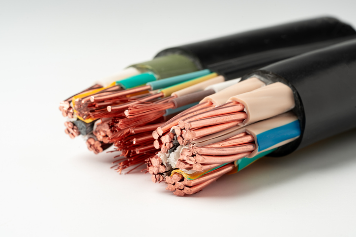
Cable, or cabling, consists of the twisting together of two or more insulated conductors.Learn More
High Voltage Wire & Cable Guide
High-voltage or HV wire and cable are necessary for many industrial applications that rely on dependable high-power transmission. Whether you’re looking for the right HV cable for your application or trying to learn more about how HV wire and cable work, we’ll break it down for you.Learn More
How to Choose the Right Wire or Cable
In selecting a wire or cable for an application, several factors should be considered. Learn More